©Pengertian Resistor adalah komponen
elektronika yang memang didesain memiliki dua kutup yang nantinya
dapat digunakan untuk menahan arus listrik apabila di aliri tegangan listrik
antara kedua kutub tersebut. Resistor biasanya banyak digunakan
sebagai bagian dari sirkuit elektronik. Tak cuma itu, komponen yang satu ini
juga yang paling sering digunakan di antara komponen lainnya. Resistor adalah
komponen yang terbuat dari bahan isolator yang didalamnya mengandung nilai
tertentu sesuai dengan nilai hambatan yang diinginkan. Berdasarkan hukum Ohm,
nilai tegangan terhadap resistansi berbanding dengan arus yang mengalir :

Bentuk
dari resistor sendiri saat ini ada bermacam-macam. Yang paling umum dan sering
di temukan di pasaran adalah berbentuk bulat panjang dan terdapat beberapa
lingkaran warna pada body resistor. Ada 4 lingkaran yang ada pada body
resistor. Lingkaran warna tersebut berfungsi untuk menunjukan nilai hambatan
dari resistor. Kode-kode warna pada resistor nantinya
akan kami jelaskan pada postingan selanjutnya.

Karakteristik utama resistor adalah
resistansinya dan daya listrik yang dapat dihantarkan. Sementara itu,
karakteristik lainnya adalah koefisien suhu, derau listrik (noise) dan
induktansi. Resistor juga dapat kita integrasikan kedalam sirkuit hibrida dan
papan sirkuit, bahkan bisa juga menggunakan sirkuit terpadu. Ukuran dan letak
kaki resistor tergantung pada desain sirkuit itu sendiri, daya resistor yang
dihasilkan juga harus sesuai dengan kebutuhan agar rangkaian tidak terbakar.
Demikian penjelasan singkat
mengenai Pengertian Resistor,
semoga pembahasan artikel kali ini dapat berguna dan bermanfaat bagi anda
semua. Baca juga artikel manarik lainnya tentang Fungsi Resistor, Jenis-Jenis Resistor dan Kode Warna Resistor.
©Jenis-Jenis Resistor pada saat ini hanya
ada 2 jenis, yaitu Fixed Resistor (Resistor Tetap) dan Variable Resistor
(Resistor Tidak Tetap). Dari dua jenis resistor tersebut di bagi lagi menjadi
beberapa bagian, berikut ini akan kami jelaskan bagian-bagian dari kedua jenis
tersebut :
Fixed Resistor (Resistor Tetap) adalah jenis resistor
yang nilainya sudah tertulis pada badan resistor dengan menggunakan kode warna
ataupun angka. Resistor ini banyak digunakan sebagai penghambat arus listrik
secara permanen. Fungsi dari resistor ini adalah sebagai pembatas arus yang
mengalir pada lampu LED. Jenis dari fixed resistor adalah :

Resistor Kawat

Resistor Kawat adalah
jenis resistor yang baru pertama kali di gunakan pada saat rangkaian
elektronika masih menggunakan tabung hampa. Bentuk fisik dari resistor ini
bervariasi dan memiliki ukuran yang cukup besar. Karena memiliki resistansi
yang tinggi dan tahan terhadap panas yang tinggi, resistor ini hanya
dipergunakan dalam rangkaian power. Sampai saat ini, jenis yang masih di pakai
adalah jenis yang memiliki lilitan kawat pada bahan keramik, kemudian di lapisi
dengan bahan semen.
Resistor Batang Karbon (Arang)

Resistor ini terbuat
dari bahan karbon kasar yang kemudian di beri lilitan dan tanda dengan kode
warna yang berbentuk gelang. Untuk dapat membaca nilai resistansi dari setiap
warna gelang tersebut dapat menggunakan tabel kode warna. Jenis resistor ini
terbentuk setelah adanya resistor kawat. Saat ini sudah jarang orang yang menggunakan
resistor batang karbon di dalam rangkaian-rangkaian elektronik.
Resistor Keramik

Dengan kemajuan
teknologi yang semakin pesat, khususnya di bidang elektronik. Pada saat ini
telah tercipta jenis resistor yang terbuat dari bahan dasar keramik atau
porselin dan dilapisi dengan kaca tipis. Karena memiliki bentuk fisik yang
kecil dan juga nilai resistansi yang tinggi, resistor ini paling banyak
digunakan dalam rangkaian elektronik. Rating daya yang dimiliki resistor
keramik sebesar 1/4 Watt, 1/2 Watt, 1 Watt dan 2 Watt.
Resistor Film Karbon

Resistor ini
merupakan hasil dari pengembangan resistor batang karbon. Sejalan dengan
perkemangan teknologi, telah terbentuklah resistor yang dibuat dari karbon dan
dilapisi dengan bahan film yang berfungsi sebagai pelindung terhadap pengaruh
luar. Nilai resistansi sudah tercantum dalam bentuk tabel kode warna. Karena
memiliki nilai resistansi yang tinggi dan juga bentuk fisiknya kecil, resistor
ini juga banyak digunakan di dalam berbagai rangkaian elektronika. Rating daya
yang dimiliki resistor ini adalah 1/4 Watt, 1/2 Watt, 1 Watt dan 2 Watt.
Resistor Film Metal

Bentuk dari resistor
film metal hampir sama dengan resistor film karbon. Hanya saja resistor ini
tahan terhadap perubahan temperatur dan memiliki tingkat kepresisian yang
tinggi karena nilai toleransi yang mencapai 1% atau 5%. Jika di bandingkan
dengan jenis Fixed Resistor lainnya, resistor ini memiliki kepresisian yang
lebih tinggi karena memilik 5 gelang warna bahkan ada juga yang terdapat 6 gelang
warna. Resistor film metal banyak digunakan dalam rangkaian elektronika yang
memiliki tingkat ketelitian tinggi, seperti alat ukur.
Variable Resistor (Resistor Tidak Tetap) adalah jenis
resistor yang memiliki nilai
resistansi berubah-ubah secara langsung dengan cara memutar atupun menggeser
tuas yang ada. Jenis dari Variable Resistor adalah :
Potensiometer

Potensiometer adalah
jenis variable resistor yang nilai resistansinya dapat kita rubah dengan cara
memutar porosnya melalui tuas yang sudah di sediakan. Pada umumnya, resistor
ini terbuat dari kawat atau karbon dan paling banyak digunakan dalam rangkaian
elektornika. Saat ini telah banyak potensiometer yang terbuat dari bahan karbon
karena memiliki ukuran yang lebih kecil dan resistansi yang cukup besar.
Perubahan nilai resistansi terbagi menjadi dua, yaitu linier dan logaritmatik.
Untuk mengetahui apakah potensiometer tersebut linier atau logaritmatik dapat
dilihat dari huruf yang tertera pada bagian belakang. Apabila tertera huruf “B”
maka potensiometer tersebut bersifat logaritmatik, sedangkan jika tertera huruf
“A” maka potensiometer tersebut bersifat linier.
Trimpot

Trimpot atau biasa di
sebut Tripotensiometer adalah resistor yang nilai resistansinya dapat berubah.
Sifat dan karakteristik trimpot tidak jauh berbeda dengan potensiometer, hanya
saja bentuk fisik trimpot lebih kecil dibandingkan dengan potensiometer.
Perubahan nilai resistansi tersebut juga dibagi menjadi 2, yaitu linier dan
logaritmatik. Untuk mengubah nilai resistansi dengan cara memutar lubang tengah
pada badan trimpot dengan menggunakan obeng.
NTC dan PTC

NTC (Negative
Temperature Coefficient) dan PTC (Positive Temperature Coefficient) merupakan
resistor yang nilai resistansinya dapat berubah apabila terjadi perubahan
temperatur di sekelilingnya. Nilai resistansi NTC sendiri akan naik apabila
temperatur di sekelilingnya turun, Sedangkan nilai resistansi PTC akan naik
jika jika temperatur di sekelilingnya naik. Kedua resiston ini paling sering
digunakan sebagai sensor karena dapat mengukur suhu atau temperatur daerah di
sekelilingnya.
LDR

LDR (Light Dependent
Resistor) merupakan resistor yang nilai resistansinya dapat berubah apabila terjadi
perubahan intensitas cahaya di daerah sekelilingnya. Itu dapat terjadi karena
intensitas cahaya yang besar dapat mendorong elektron untuk menembus
batas-batas pada LDR. Dengan begitu, nilai resistansi akan naik jiga intensitas
yang diterima sedikit. Sedangkana nilai resistansi dari LDR akan turun jika
intensitas cahaya yang diterima banyak. Resistor LDR sendiri banyak digunakan
sebagai sensor cahaya, khususnya pada lampu taman.
Demikian penjelasan singkat mengenai Jenis-Jenis
Resistor,
semoga artikel yang barusan di sampaikan dapat berguna dan bermanfaat bagi anda
semua. Baca juga artikel menarik lainnya, seperti Pengertian
Resistor, Fungsi
Resistor dan Kode
Warna Resistor.
©Rangkaian Seri dan Paralel
Resistor serta Cara Menghitung Nilainya
Resistor adalahKomponen Elektronika yang paling
sering ditemui dalam rangkaian Elektronika. Fungsi dari Komponen Resistor
adalah sebagai penghambat listrik dan juga dipergunakan sebagai pengatur arus
listrik dalam rangkaian Elektronika. Satuan pengukuran Resistor (Hambatan)
adalah OHM (Ω). Dalam Rangkaian Elektronika, Resistor atau Hambatan ini sering
disingkat dengan huruf “R” (huruf R besar).
Nilai Resistor
yang diproduksi oleh Produsen Resistor (Perusahaan Produksi Resistor) sangat
terbatas dan mengikuti Standard Value Resistor (Nilai Standar Resistor). Jadi
di pasaran kita hanya menemui sekitar 168 jenis nilai resistor. Berikut ini
adalah tabel Standard Value Resitor (Nilai Standar Resitor) yang terdapat di
pasaran.
Tabel Nilai
Standar Resistor
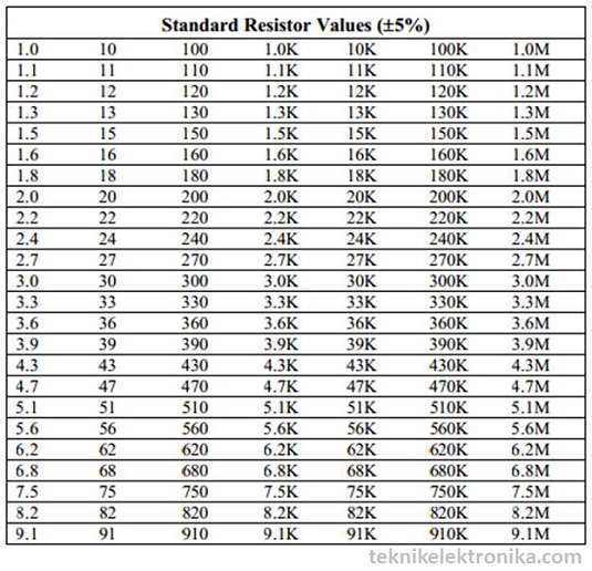
Jadi bagaimana
kalau nilai Resistor yang kita inginkan tidak terdapat di pasaran? Contohnya
400 Kilo Ohm, 250 Ohm, ataupun 6 Kilo Ohm. Nilai-nilai Resistor yang disebutkan
ini tidak terdapat dalam daftar Standard Value Resistor sehingga kita tidak
mungkin akan menemukan nilai-nilai Resistor tersebut di Pasaran. Untuk mengatasi
hal ini kita perlu menggunakan Rangkaian Seri ataupun Rangkaian Paralel
Resistor untuk mendapatkan Nilai Resistor yang kita inginkan.
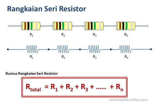
Rangkaian Seri Resistor
Rangkaian Seri
Resistor adalah sebuah rangkaian yang terdiri dari 2 buah atau lebih Resistor
yang disusun secara sejajar atau berbentuk Seri. Dengan Rangkaian Seri ini kita
bisa mendapatkan nilai Resistor Pengganti yang kita inginkan.
Rumus dari Rangkaian Seri Resistor adalah :
Rtotal = R1 + R2 + R3 + ….. + Rn
Dimana :
Rtotal = Total Nilai Resistor
R1 = Resistor ke-1
R2 = Resistor ke-2
R3 = Resistor ke-3
Rn = Resistor ke-n
Rtotal = Total Nilai Resistor
R1 = Resistor ke-1
R2 = Resistor ke-2
R3 = Resistor ke-3
Rn = Resistor ke-n
Berikut ini
adalah gambar bentuk Rangkaian Seri :
Contoh Kasus untuk menghitung
Rangkaian Seri Resistor
Seorang Engineer
ingin membuat sebuah peralatan Elektronik, Salah satu nilai resistor yang
diperlukannya adalah 4 Mega Ohm, tetapi Engineer tidak dapat menemukan Resistor
dengan nilai 4 Mega Ohm di pasaran sehingga dia harus menggunakan rangkaian
seri Resistor untuk mendapatkan penggantinya.
Penyelesaian :
Ada beberapa
kombinasi Nilai Resistor yang dapat dipergunakannya, antara lain :
1 buah Resistor
dengan nilai 3,9 Mega Ohm
1 buah Resistor dengan nilai 100 Kilo Ohm
Rtotal = R1 + R2
3,900,000 + 100,000 = 4,000,000 atau sama dengan 4 Mega Ohm.
1 buah Resistor dengan nilai 100 Kilo Ohm
Rtotal = R1 + R2
3,900,000 + 100,000 = 4,000,000 atau sama dengan 4 Mega Ohm.
Atau
4 buah Resistor
dengan nilai 1 Mega Ohm
Rtotal = R1 + R2 + R3 + R4
1 MOhm + 1 MOhm + 1 MOhm + 1 MOhm = 4 Mega Ohm
Rtotal = R1 + R2 + R3 + R4
1 MOhm + 1 MOhm + 1 MOhm + 1 MOhm = 4 Mega Ohm
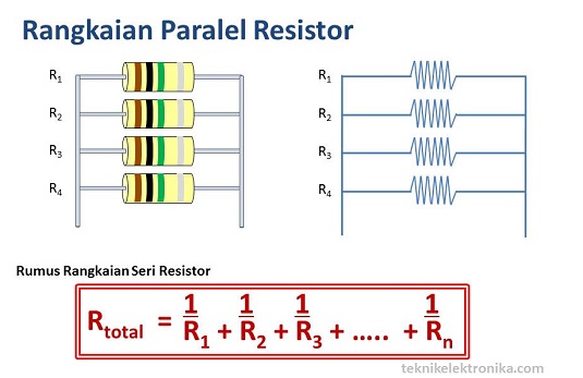
Rangkaian Paralel Resistor
Rangkaian Paralel
Resistor adalah sebuah rangkaian yang terdiri dari 2 buah atau lebih Resistor
yang disusun secara berderet atau berbentuk Paralel. Sama seperti dengan
Rangkaian Seri, Rangkaian Paralel juga dapat digunakan untuk mendapatkan nilai
hambatan pengganti. Perhitungan Rangkaian Paralel sedikit lebih rumit dari
Rangkaian Seri.
Rumus dari
Rangkaian Seri Resistor adalah :
1/Rtotal = 1/R1 + 1/R2 + 1/R3 + ….. + 1/Rn
Dimana :
Rtotal = Total Nilai Resistor
R1 = Resistor ke-1
R2 = Resistor ke-2
R3 = Resistor ke-3
Rn = Resistor ke-n
Rtotal = Total Nilai Resistor
R1 = Resistor ke-1
R2 = Resistor ke-2
R3 = Resistor ke-3
Rn = Resistor ke-n
Berikut ini
adalah gambar bentuk Rangkaian Paralel :
Contoh Kasus untuk Menghitung
Rangkaian Paralel Resistor
Terdapat 3
Resistor dengan nilai-nilai Resistornya adalah sebagai berikut :
R1 = 100 Ohm
R2 = 200 Ohm
R3 = 47 Ohm
R1 = 100 Ohm
R2 = 200 Ohm
R3 = 47 Ohm
Berapakah nilai
hambatan yang didapatkan jika memakai Rangkaian Paralel Resistor?
Penyelesaiannya :
1/Rtotal = 1/R1 + 1/R2 + 1/R3
1/Rtotal = 1/100 + 1/200 + 1/47
1/Rtotal = 94/9400 + 47/9400 + 200/9400
1/Rtotal = 341 x Rtotal = 1 x 9400 (→ Hasil kali silang)
Rtotal = 9400/341
Rtotal = 27,56
1/Rtotal = 1/100 + 1/200 + 1/47
1/Rtotal = 94/9400 + 47/9400 + 200/9400
1/Rtotal = 341 x Rtotal = 1 x 9400 (→ Hasil kali silang)
Rtotal = 9400/341
Rtotal = 27,56
Jadi Nilai
Hambatan Resistor pengganti untuk ketiga Resistor tersebut adalah 27,56 Ohm.
Hal yang perlu
diingat bahwa Nilai Hambatan Resistor (Ohm) akan bertambah jika menggunakan
Rangkaian Seri Resistor sedangkan Nilai Hambatan Resistor (Ohm) akan berkurang
jika menggunakan Rangkaian Paralel Resistor.
Pada Kondisi
tertentu, kita juga dapat menggunakan Rangkaian Gabungan antara Rangkaian Seri
dan Rangkaian Paralel Resistor.
Untuk mengetahui
cara membaca kode warna dan kode angka Resistor, silakan membaca artikel “Cara
menghitung Nilai Resistor“
Applications
of resistors
Precharge Resistors
A typical power
supply circuit is shown below. Rush current flows to charge the capacitor
having a large value, when the power is turned on. A resistor is used to eliminate
the rush current. This resistor should withstand the rush current of several
ten's of Amperes and neither emit smoke nor catch fire even when the switching
transistor breaks down to be subjected to a larger current. From these
standpoints, wire-wound ceramic cement resistors with excellent pulse
withstanding, BGR, BWR and CW are recommended. Wire-wound
with a built-in fuse ceramic resistors WF are also recommended
to protect from continuous over-current. Contact us when you select a
resistor.

Power Type Resistors
Power type Resistors
include wire-wound: CW, and metal-oxide
film: MOS MO. Either
type has different electrical characteristics, which should be selected
depending on your circuit.
Wirewound type applies metal resistive wire to achieve excellent stability and pulse resistant characteristics. Because resistive wire is wounded in coil shape, inductance or capacitance are relatively large and is sometimes affected by the frequency characteristics of the circuit. The product of high resistance generally tends to have long wounded resistive wire, and is more likely to be large with low resonant characteristics. Pay attention to the influence on frequency characteristics when you use wirewound type for load resistors of voltage amplifier requiring flat frequency characteristics. Non-inductive type wirewound resistor RW_N, with improved frequency characteristic, is recommended.
Metal-oxide type resistors are physically small sized, excellent in frequency characteristics, and the resistance value can be high while they have inferior pulse resistance characteristic when compared to wire-wound type resistors. To compare the possible resistance range, wire-wound types are rather low between several ten's of Ω m and several kΩ while that of metal-oxide types covers from several ten's of ohm to several hundred of kohm.
Our ceramic cement type resistors include both wire-wound resistors BGR BWR metal-oxide resistors BSRwhich are used for different applications depending on resistance range.
Application example of video
output circuit

In
Western countries, secondary circuit is insulated by trans from primary circuit
connected to commercial power supply. In electronic devices like audio or
video, with outer antenna or various input/output terminals that people can
easily touch, people can get electric shock if the secondary circuit retains
electricity. By connecting ground and secondary circuit, the secondary circuit
is required not to be charged. Discharge resistor is used for this connecting
area.
Typical
inserting point of discharge resistors is the point between the ground of
primary circuit and secondary circuit as below. The ground of secondary circuit
is connected to e.x. terminal that people can easily touch normally.
Commercial power supply is grounded galvanically so discharge resistors prevent
secondary circuit from being electrical-charged, which avoids electrical shock
hazard.
Discharge
resistors are also used for the area that crosses over the contact gap of
switch of the main power supply. This is to avoid arc when it is OPEN. It
sometimes connected between the different pols of power supply at primary
side.
The resistors used
with this purpose are required to keep stable resistance under overload and
required to be tested according to IEC60065 14.1. RCR50EN and RCR60 are discharge
resistors comformed to the standard.

Snubber
circuit
Snubber circuit is
the circuit connected to both terminal of the element which produces surge
voltage in order to absorb surge energy generated by switching. Snubber
circuits include serial circuit(RC snubber) with resistor and capacitor, the
circuit connected with RC and diodes to clip the top of the surge voltage. See
inside of the circles in the image below. For example, rectifying diodes in the
secondary side of switching power supply can be the source origin of surge by
quick change of voltage and current caused by switching ON/OFF. RC snubber
circuit is used for this surge voltage absorption. A snubber circuit is
required to absorb noise but with minimum energy loss and resistors used in
such circuit should have both optimized constant and considerations for
safety.
Flame retardant type resistors are required to control the smoking or firing of resistors when a capacitor or semiconductor is short-circuited depending on switching voltage and the constant of snubber circuit. Metal oxide film resistors MO MOS have excellent heat resistance so therefore the smaller type can be used if the allowable power is the same. Those are suitable for snubber circuit because the products apply flame retardant coating. Resistors used in RC snubber circuit are required to have surge resistance characteristics, which requires attention.

Flame retardant type resistors are required to control the smoking or firing of resistors when a capacitor or semiconductor is short-circuited depending on switching voltage and the constant of snubber circuit. Metal oxide film resistors MO MOS have excellent heat resistance so therefore the smaller type can be used if the allowable power is the same. Those are suitable for snubber circuit because the products apply flame retardant coating. Resistors used in RC snubber circuit are required to have surge resistance characteristics, which requires attention.
Gain determination of amplifier circuit
See the images of
inverting amplifier circuit and non inverting amplifier circuit that apply OP
amp as below. Amplifying gain is determined by the ratio of R1 and R2.
To achieve the necessary gain without any adjustment, each resistor in R1 or R2 should have high precision and is unlikely to be affected by the temperature. Metal film type resistors RN73 RN73H are suitable because of the high precision and excellent temperature characteristics.
There is also compound type resistors which means one chip resistor include two resistors in pair. This type of resistor achieve excellent relative precision and TCR tracking because two resistors are included. CNN2A has two embedded resistors with TCR of ±25x10-6/K, which becomes 5x10⁻⁶/K or smaller in relative. KPC series has more resistors in one package, which enables improved relative precision and high density mounting.

Noise of resistors is
divided into thermal noise and current noise.
Thermal noise is logically determined by resistance, absolute temperature and frequency range, and has no relation with resistor material. The effective value in unit interval of frequency is extremely small and distributed uniformly in frequency domain, which leads to main factor of deterioration of S/N in broad band amplifier of wireless frequency. Normally, no problem occurs in low frequency range under audio frequency.
The current noise, on the contrary, depends much on material, the lower the frequency, the larger the noise becomes. In the frequency range under kHz, the effective value of unit interval of frequency is larger than thermal noise; especially under a few Hz, it increases incomparably. Optical detecting circuit as below which amplifies micro detecting signal with large gain, or applications like elctrocardiographic monitors which handle micro voltage near direct current, current noise rather than thermal noise would be the main factor of deterioration of S/N. In these purposes, thin film chip resistors with excellent current noise characteristics like RN73, RN73H orMF, RNS, and MRS are suitable.
Example of circuit easily
influenced from current noise(optical detecting circuit)

Digital circuit
Pull-up Resistors / Pull-down Resistors /
Damping Resistors
Buss in the digital
circuit plays a role to transfer data in CPUs, memories and peripheral devices.
Resistor of 1k to 100kohm is inserted between power supply, ground and signal
wire(pull-up/pull-down resistor) to stabilize the signal electropotential of
buss, or resistor of tens to hundreds is used between signal wire and ground to
align the impedance of signal wire and LSI.(terminal resistor). Resistors of 10
to 33 ohm are used in parallel in signal wire to adjust waveform(damping
resistor).
Parallel buss consists of plural signal wires; each of signal wire requires pull-up/pull-down, terminal resistor, damping resistor, which needs much space. Chip network resistors are suitable for such areas.
For 8-bit width pull-up resistor/terminal resistor, when the necessary area for 8 pieces chip resistors(size 2012) is 100%, two chip network resistors CN2A4 enables to reduce the area by around 20%.(* calculated when the interval of products is 0.5mm and the dominant area is 0.5mm from the product peripheral). This will also reduce the number of mounting components, which leads to the mounting cost reduction. For 8bit width pull-up/terminal resistors, suppose the necessary surface for 8 pcs of 2012 chip resistors is 100%, two chip network resistorsCN2A4 enables to save about 20% surface(calculated the product interva for 0.5mm and product surroundings 0.5mm). Less number of mounting components will also lead to mounting cost reduction.

Tidak ada komentar:
Posting Komentar